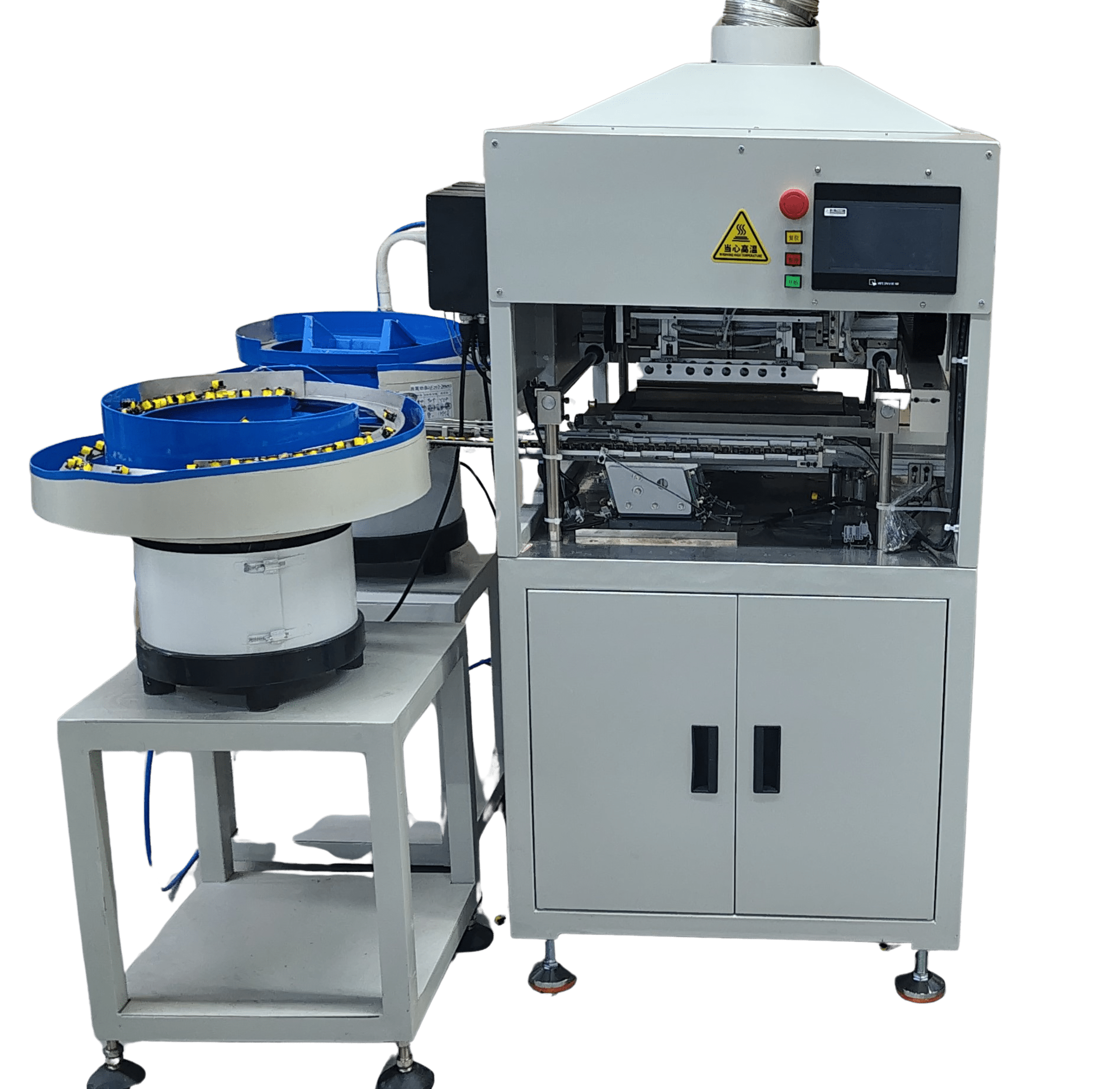
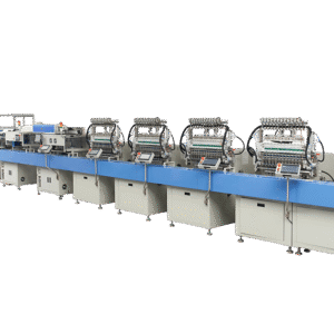
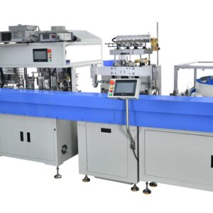
In this fully automatic soldering machine, no manual work is involved, loading-unloading, fluxing & soldering all operations are automatic.
Solder pot is made of titanium material which can hold very high temperature of tin with great life of min. 15 years.
Soldering arm is rotary type which helps to solder with different angles, dip position is accurate, and soldering dip time is also programmable.
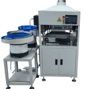
One machine can operate with two types of different vibrator bowls, which works independently and unload in different bins.
Transformer Coil Automatic Dip Soldering Machine EE EFD PQ Ferrite magnetic coil Tinning
Working Video of the Machine
Main devices/Parts on Machine Description
Amplifier and Fiber-optic:
Supporting the use with fiber-optic.
Function:
When feeding channel is full of product, it will output a signal to the programmable controller (PLC), to execute a material grasp. It can be adjusted to sense the distance of material (close or far distance).
The indicator of orange light is lit if it senses material and will output a signal.
L and D switch uses:
When the switch is on D status, it will output a force status. (If there are no material being close, it will output a signal, when material approaching to the signal output, it will stop output signal), D output is contrary to L output, therefore in normal use, L status shall be selected in status.
Servo Motor:
Distribution box with supporting the use of servo drive, its function primarily handles the material after the grasp on a forward & backward sliding movements, it is fast and accurate in position!
It is driven by a synchronous belt wheel. If there is synchronization between the loose wheel and servo motor shaft position appears inaccurate traverse phenomenon.
Stepping Motor:
It is to drive an up & down movements of a mechanical clamper.
Similarly, there is a screw loose synchronization between wheel and the motor will cause the phenomena of improper soldering (dipping height not even) and grasping the material in leaning position.
Robot cylinder:
Functions of grasping the product, clipping mouth with strip pad to avoid any damage on transformers & copper wire!
Transformer Chock Coil Dip Soldering Machine Manufacturer India
Flux cylinder:
It drives the fluxing cup in vertical movement (up/down). There are two corresponding sensors on all cylinders (except robot cylinder), sensor located at end of cylinder is called “lower limited”, sensor located front of cylinder called “upper limited”.
If cylinder is on movement status, but senor not lit, the machine will stop operation and display an error message.
Solder cup cylinder:
By lifting up solder cup (up/down) to achieve soldering process, it delivers a highly consistent tin solder level on each cycle.
When the solder cup cylinder rises up and the limited sensor lit, the stepping motor reaches to the dipping level of soldering; it then will start counting as a soldering time.
Sweep cylinder (clean dross forward/backward)
It is a round cylinder that drives a sweeping plate to move forward and backward to clean dross before soldering.
When the cylinder extends and reaches to the corresponding sensor (upper limited), it will lit and movement forward stops; then cylinder moves backward until reaching to lower limited on sensor, the movement is completed.
Sweep cylinder (up/down movement)
Same as above
Sensor:
All cylinders of status corresponding to sensors should be lit, otherwise action cannot continue and the failure red text prompts up! Make sure all sensors are on position and light is lit!
Motor home sensor only works when it is back to home position. Return back to home position is to complete a cycle; it ends as “0”. Each positional parameter corresponding to a position, it is an absolute position.
Temperature controller:
Functions with the temperature probe, solid state relays, heat pipe used.
Featuring at AT auto tuning function indication, OUT heating output indications, AL temperature reaches & output signal, PV current tin solder pot temperature display, SV set temperature display.
Wiring/distribution box:
The description of parts from left to right and from top to bottom in the box as shown on picture, they are the programmable controller (PLC), relays, terminal blocks, solid state relays, fuse holder, power switch leakage protection, servo motor drives, stepping motor drives, switching power supply (stepping motor power, solenoid valve sensor touch screen power).
Filter:
It contents air supply connector and air pressure indicator.
The left side is the air filter chamber, right side for the oil chamber, by adding quality of lubricants can improve the life of the cylinder solenoid valve.
EFD PQ EE Core Transformer Automatic Winding Machine with Insulation sleeve tube & margin Tape
Software Parameters Adjustment
Time Parameters:
Grasp material time: It is a setting time counts only when the mechanical clamper reaches and grabs material from feeding channel (counts time), then return to origin position.
Flux time: It is a time setting counts only when the ceiling sensor on flux cylinder lit, up down motor reaches to the exact height of fluxing level (counts time), when time’s up, motor returns to origin position and flux cylinder goes down.
Release material time: It is a time setting counts for releasing soldered material which waiting for cooled down to release on conveyor belt.
Unloading time: in terms of Conveyor rotation time. It is a time setting only after released material on conveyor belt, and stepping motor returns back to origin position, the conveyor will start rotate.
If the parameter is 0, the conveyor belt does not rotate.
Feed sensor time: When the product is fully packed in feeding channel, optical sensor will output a signal (amp orange lights), start delay until stepping motor comes down to pick up material.
No angle solder time: The rotary motor does not perform an angle rotation; it directly goes down to the soldering position, and then pauses. Time counting starts.
Clockwise soldering time:: It is a time setting counts when the rotary motor goes clockwise direction then down to soldering position, pause and time counts.
Reversal of soldering time:: It is a time setting counts when the rotary motor goes reversal/ anti-clockwise direction then down to soldering position, pause and time counts.
Transformer Coil Automatic Dip Soldering Machine EE EFD PQ Ferrite magnetic coil Tinning
Speed Parameters:
Grasp material up/down speed: Control the moving speed of stepping motor going down to pick up material & returns back to original position.
Release material up/down speed: It is to control the moving speed of upward & downward to release material on conveyor belt.
Flux up/down speed: Control the moving speed of stepping motor going up and down to dip flux.
“A” soldering speed: For feeder of “A” product, the moving speed from origin position to soldering position. And it also to control the moving speed away from soldering point.
This is the same as applying to “B” product setting as above.
“A” separate speed: It is a leaving upward speed movement control after dip soldering position.
This is the same as applying to “B” product setting as above.
Turn rate of grasp material: It is a returning backwards speed movement control to the station of grasp material.
Rotation speed: Control the moving speed of rotary motor turning and returning to origin position
Traverse speed: Control the moving speed of the distance from the grabbing material station to the flux station, soldering station and material release position respectively.
Traverse soldering speed: Control the moving speed of the distance from the flux station to the soldering station.
Traverse material release speed: It is to control the moving speed from soldering position to material release position.
Vibrator Bowl Installation & Adjustment
Place the stand on a flat and stable floor. (if stand included)
Place the vibrator on the stand, set and level the height corresponding and fit to the bobbin feeding chute by adjusting the screw legs.
Connect the power to the vibrator and fill bobbins into it.
Turn ON power and see it is working and delivering bobbin to the chute.
Adjust carefully the connection at feeding outlet to chute. (If it is not well adjustment, bobbins cannot be delivered smoothly to the chute)
More details, please contact freely :
DEPTRONICS TECHNOLOGIES
Contact : Deepanshu Saxena
Mobile : +91-8800622761
WhatsApp : https://wa.me/918800622761
Email : [email protected]


Reviews
There are no reviews yet.