


Why Automation for Solenoid Coil Manufacturing?
Before technical detail, understand the benefits clearly:
-
Consistency & Quality: Automation ensures identical winding geometry, uniform turns, and exact tap placements — critical for coil electrical performance (inductance, resistance).
-
Higher Throughput: Multi-spindle automatic machines increase production many times over compared to manual winding. 12–24 spindles run concurrently; cycle times drop dramatically.
-
Reduced Labor Cost and Human Error: One operator can supervise multiple machines/lines; rejects decrease.
-
Process Integration: Automatic transfer to soldering, pin bending, testing and packaging reduces handling damage and increases takt time.
-
Traceability & Test Data: Integrated testing (LCR, DC resistance) and CCD inspection provide quality logs and reduce field failures.
-
Scalability: Modular lines allow capacity growth (add spindles or additional soldering stations).
Given these advantages, choosing a Fully Automatic Solenoid Coil Winding Machine Manufacturer in India is a strategic investment for any serious OEM.
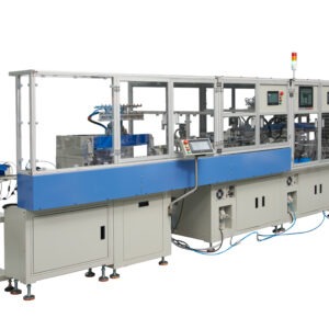
High-Level Production Flow (End-to-End)
A modern fully automatic solenoid coil production line typically follows this sequence:
- Auto bobbin feeding.
- Terminal pin insertion (auto).
- Loading onto mandrel → multi-spindle programmable winding (12 / 16 / 20 / 24).
- Auto unload from winding turret → load into conveyor / transfer to soldering station.
- Rotary dip soldering with auto flux dosing.
- Pin bending / crimping / pressing.
- Electrical testing (LCR / DC resistance / hipot where applicable).
- CCD visual inspection for solder joint & winding faults.
- Final unload into protective tray and packaging.
Below we deep-dive into each stage with technical detail — tooling, sensors, control logic, cycle timers, and engineering choices.
Working Video of Solenoid Coil Production Line
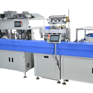
Detailed Machine Working / Process Flow (Main Section)
1. Auto Bobbin Feeding — First Mile of the Line
Purpose: Smooth, accurate, timed supply of empty bobbins into the production line with correct orientation.
Feeding methods:
-
Vibratory bowl feeder with orienting tracks: ideal for high speed and varied bobbin profiles. Vibratory motion and specially designed tracks orient bobbins to the required position and hand them to an indexing conveyor.
-
Rotary feeder / carousel: compact solution for small footprints; bobbins loaded into pockets and rotated to pick points.
-
Pick-and-place robot from trays: flexible for varied bobbin geometries and changeovers.
Key components:
- Feed hopper with level sensor (ultrasonic / IR) and low-level alarm.
- Orienting track with mechanical guides to hold bobbin orientation.
- Pneumatic or servo-driven pick head or pusher to transfer bobbin to the loading station.
- Presence sensors (photoelectric, inductive) to confirm correct bobbin.
- Reject mechanism for malformed or upside-down bobbins.
Control & logic:
- Set feed rate to maintain continuous line flow.
- Interlocks ensure the winding turret or mandrel is ready before feed.
- Auto retry logic: if orientation not corrected within two attempts, push to reject bin to avoid downstream stoppage.
2. Terminal Pin Insertion — Precision Mechanical Insertion
Purpose: Insert terminal pins into the bobbin terminals prior to winding. Correct insertion ensures soldering and final electrical contact reliability.
Approaches:
-
Pneumatic insertion head: High speed with controlled stroke and force. Good for standard pins and long production runs.
-
Servo or linear motor insertion: Greater control over insertion depth, force profiling, and variable pin types.
-
Robotic insertion (SCARA/6-axis): Best for complex orientations or multiple pin positions.
Fixtures & tooling:
- Pin feed from a vibratory bowl or collated tape feeder.
- Insertion mandrel for supporting bobbin and ensuring alignment.
- Force sensor or load cell on the insertion tool to detect incorrect insertion, missing pins, or excessive resistance (which could indicate a broken pin or misalignment).
Sensors & checks:
- Optical sensor or mechanical detector to verify pin presence after insertion.
- Limit switches to monitor full stroke.
- Immediate reject path if insertion force exceeds pre-set limit.
Control routines:
- PLC coordinates pin feed and insertion timing with bobbin presence signal.
- Retry attempts: if insertion fails due to minor misalignment, the controller can attempt re-alignment and re-insert up to a defined number of times before rejecting.
- Option to mark feed time and insertion success in the traceability log.
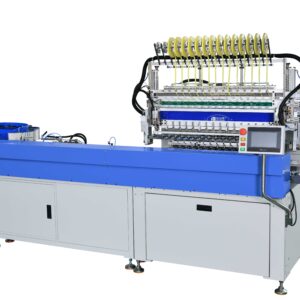
3. Multi-Spindle Winding — 12 / 16 / 20 / 24 Spindle Configurations
Purpose: Simultaneous, repeatable winding across multiple spindles to multiply throughput.
Key architecture:
-
Spindle bank: Array of spindles (12/16/20/24) arranged on a single turret or linear head. Each spindle has independent tension and control.
-
Programmable winding head: Every spindle can execute defined patterns — single layer, bifilar, multilayer, taps at defined turns, and more.
-
Mandrel / bobbin clamping: Pneumatic or servo clamps hold bobbin on mandrel during winding if required.
Winding patterns supported:
- Single winding (standard solenoid coil).
- Bifilar / multi-wire configurations.
- Layered winding with tape insertion in between layers.
- Lapped winding for uniform density.
Cycle time & throughput:
-
Throughput depends on turns per coil, wire gauge, and spindle speed. For example, a 12-spindle machine winding 150 turns per coil at 12000 RPM effective lay speed can produce hundreds of coils per hour per spindle bank. Multi-spindle multiplies that throughput.
Monitoring & alarms:
- Wire break detection using IR/photoelectric or micro-switch tension loss detection.
- Over-current / drive alarms for servo faults.
- Wire guide position sensors to detect misfeeds.
4. Auto Unload and Transfer to Soldering Station
Purpose: Smooth, synchronized transfer of wound bobbins from winding station to soldering module with minimal handling.
Transfer mechanisms:
-
Robotic pick & place (6-axis or SCARA): Gentle picking, orientation correction, and transfer to conveyor or directly to solder pot fixtures.
-
Linear conveyors with indexing plates: The winding turret unloads directly onto an indexing conveyor which moves coil pockets into the soldering station.
-
Rotary transfer indexes: Circular plate with pockets that rotate to successive stations (winding → transfer → soldering).
Clamping & seating:
-
Special grippers or vacuum noses ensure secure pick up without damaging wound coils. Soft jaws or rubber pads prevent wire abrasion.
Synchronization & buffer:
-
Buffers (accumulation conveyors) help decouple winding cycle time from soldering cycle time, preventing line stoppages. PLC logic manages buffer levels and flow control.
Quality checks before transfer:
- Quick continuity check or loop test to ensure no open circuits before soldering.
- Presence & orientation sensors ensure correct seating for soldering.
5. Rotary Type Dip Soldering with Auto Flux (Rotary Dip Soldering Station)
Purpose: Make robust solder joints for terminal pins to the winding tails. Rotary dip provides higher throughput and uniform soldering.
Rotary dip soldering layout:
-
A rotary index table with fixtures (pockets) holds the coils and rotates them sequentially through stations:
-
Flux dosing / spray: Precisely dispense flux to terminal/pin area.
-
Preheat (optional): IR or convection preheating to drive off solvents and stabilize temperature.
-
Solder dip: Dip the terminal area into molten solder pot.
-
Cooling / wipe: Air knives or wipe station to remove excess solder and shape joints.
-
Inspection (CCD or vision) immediate post-soldering.
-
Solder pot:
-
Temperature control with PID controllers and thermal shielding to maintain stable solder bath temperature (e.g., 350–4000°C for Sn63/Pb37 or higher for lead-free solder).
-
Flux residue control and skimming arrangement.
Solder joint quality controls:
- Wave height and dip dwell time programmable to avoid solder bridging.
- Air knives / wipers to create proper fillet and remove excess solder.
- Solderability sensors detect insufficient fillet or incomplete wetting.
Safety features:
- Fume extraction with local exhaust to control flux fumes.
- Interlocks to prevent operator access while solder pot is active.
- Thermal shields and emergency stop logic.
Throughput note: Rotary indexing allows continuous soldering of multiple coils per minute depending on index speed and dwell times. Pairing the rotary station with buffer conveyors optimizes overall takt time.
6. Auto Pin Bending or Pressing
Purpose: After soldering, terminal pins often require bending or forming to final geometry (e.g., J-bend, crimp, right angle) for PCB mounting or connector assembly.
Mechanisms:
-
Servo-driven forming station: High precision, programmable forming profiles, adjustable for different pin diameters and bending radii.
-
Pneumatic press with forming die: Cost-effective for high volume, fixed geometry bending.
-
Robotic forming tools: For complex bend sequences or multiple pins.
Quality checks:
- Vision or mechanical gauge to verify bend angle & clearance.
- Resistance / continuity check post-bend to ensure no damage to internal windings.
7. Testing — Electrical & Functional Validation
Purpose: Ensure each coil meets electrical parameters — DC resistance, inductance, Q factor (if required), insulation resistance, and continuity. Testing eliminates defects early and provides traceability.
Types of tests:
-
DC Resistance (DCR): Low resistance measurement using four-wire (Kelvin) method for precision.
-
Inductance (L) & Q factor: Using LCR meters or bridge testers for frequency-dependent validation.
-
Insulation resistance / Hipot (where necessary): High voltage test for dielectric integrity (typically for safety-critical coils).
-
Continuity test: Quick pass/fail for open circuits.
-
Functional test: For complete solenoid assemblies, actuation and stroke tests may be included on the line.
Automatic sorting:
-
Failures are routed to reject bins for rework or scrap.
8. CCD Check (Computer Vision / Optical Inspection)
Purpose: Visual verification of winding quality, solder fillet, pin position, and presence of foreign materials. CCD cameras detect surface defects faster than manual inspection.
Common CCD checks:
-
Solder joint fillet presence & wetting – check for insufficient solder, bridging or cold solder joints.
-
Pin position & bend accuracy – ensure pins are within tolerance on x/y axis.
-
Winding neatness – detect loose turns, wire crossing or smashed insulation.
-
Label & marking verification – check product codes, orientation marks.
System architecture:
- High-resolution CCD cameras with telecentric lenses for distortion-free measurement.
- Illumination systems: ring lights, backlights, and diffusers to get consistent images.
- Image processing algorithms and pattern matching to identify defects; configurable thresholds per product family.
Integration into workflow:
- CCD systems mounted post-soldering and post-bending stations for in-line inspection.
- Reject logic: immediate diversion to rework station if defect identified.
- Data logging of images for audit and troubleshooting.
Benefits: Lower false rejects compared to human inspection, consistent 24×7 performance, immediate feedback to process owners.
9. Unload into Tray for Product Safety & Packaging
Purpose: Final handling to ensure product protection and ease of downstream packaging and shipping.
Tray types & methods:
-
ESD safe trays with pockets sized to coil geometry, preventing movement and scratching.
-
Blister trays for additional mechanical protection.
-
Tape & reel options for electronic assembly customers (if required).
Unloading solutions:
-
Pick & place robot to accurately place coils into trays with correct orientation.
-
Gravity chute into fixed trays for simple operations (less precise, but cost effective).
-
Indexing conveyor with tray pockets that accept finished coils as they arrive.
Safety & QA:
- Part presence sensor in each tray pocket to ensure completeness.
- Tray level sensor to avoid overflow.
- Packing labels and batch codes printed or applied automatically for traceability through laser printer.
Optional Add-Ons & Assembly Line Extensions
A real strength of a fully automatic solenoid coil manufacturing machine line is the ability to offer integrated assembly solutions beyond coil winding. Deptronics and similar manufacturers provide modular add-ons:
1. Riveting & Mechanical Part Assembly
- Auto rivet feeding and rivet insertion stations for mechanical fastening (for solenoid plunger caps or assembly housings).
- Press stations with force sensing to avoid deformation.
- Spiral screwdrivers and nut-feeding modules for small mechanical assemblies.
2. Complete Subassembly Cells
-
Combine coil winding, soldering, pin forming, rivet assembly and final mechanical housing insertion in a single autopilot line.
3. Conveyorized End-of-Line Packaging
-
Automated cartoning and labelling for direct dispatch to OEM assembly lines.
These add-ons make the line a one-stop solution for customers looking to move from manual or semi-automatic processes to fully automated production, reducing touch points and increasing reliability.
Productivity, Example Calculations
Manufacturers ask: “How fast will this pay back?” Below is a worked example to estimate throughput and simple ROI. Numbers are illustrative — actual values depend on product specifics and local costs.
Assumptions (example product):
- Machine configuration: 12-spindle winding machine with rotary dip soldering.
- Coil spec: 500 turns, wire gauge AWG 35.
- Winding cycle per 12 coil : 30 seconds.
- Additional processing (soldering + bending + testing): 03-04 seconds per coil (line balanced).
- Effective takt time per 12 coils (line): 35 seconds
- Operating hours per day: 16 hours (two shifts).
- Operating days per year: 300.
Throughput calculation:
- Coils per hour = 1100-1200 coils per hour.
- Daily output = 1100 × 15 = 16,500 coils per day.
- Annual output = 16,000 × 300 = 4,800,000 coils per year.
Note: This is a simplified example. Real payback calculations must factor in:
- Raw material costs (copper wire, bobbins, terminals, solder).
- Labour savings vs previous manual process.
- Energy costs.
- Maintenance and consumables.
- Floor space and utilities.
Even with conservative assumptions, well-organized automated lines typically pay back within 6–24 months depending on production volumes and product complexity.
Case Studies / Use-Cases (Representative)
Case A — Automotive Solenoid Supplier (High Volume):
Configured a 24-spindle winding machine with dual rotary dip soldering stations and inline CCD inspection. Achieved a 4× throughput increase and reduced rejects by 70% within three months post-commissioning.
Case B — Appliance Manufacturer (Medium Volume, Multiple SKUs):
Used a 12-spindle modular line with quick-change fixtures. Reduced manual labour by 65% and achieved consistent DCR within ±1% tolerance across 10 SKUs.
Case C — Contract Manufacturer (Small Batch Custom Orders):
Installed a 16-spindle machine with robotic pick & place for flexible batch sizes; recipe management enabled quick changeover between customer families.
These real-world use cases demonstrate typical benefits from a Fully Automatic Solenoid Coil Winding Machine Manufacturer in India.
Frequently Asked Questions (FAQ)
Q1: Which spindle configuration should I buy — 12, 16, 20 or 24?
A: Choose based on volume and floor space. 12/16 suits medium volumes and offers lower capex. 20/24 are for high volume. Also consider wire gauge and cycle time — more spindles help when winding time dominates.
Q2: Can the machine handle different bobbin sizes?
A: Yes — with quick-change mandrels and adjustable fixtures. Deptronics provides changeover kits and recipes for multiple sizes.
Q3: How is wire break detected and handled?
A: Through tension sensors, optical detectors and wire guides. On detection, the machine pause and sounds alarm.
Q4: Is lead-free solder supported?
A: Yes. Temperature profiles, solder pots and flux selection are configured for lead-free alloys.
Q5: What is the typical lead time for a full production line?
A: Varies with customization — typically 50 to 70 working days for standard line configurations; longer for highly custom automation.
Q6: Do you provide trials or sample runs before purchase?
A: Reputable manufacturers usually offer prototype runs, sample processing and FAT (Factory Acceptance Test) before shipment.
Why Choose Deptronics Technologies — Your Indian Manufacturer & Partner
As a Fully Automatic Solenoid Coil Winding Machine, Deptronics offers:
-
Tailor-made solutions: Machines designed for the exact bobbin geometry and functional requirements.
-
Strong service footprint in India: Commissioning, spare parts, and trained technicians available across all over India major industrial regions.
-
End-to-end assembly & testing integration: From bobbin feeding to tray unloading — a single integrator saves time and aligns responsibility.
-
Transparent ROI modeling: Deptronics helps customers estimate throughput, cost per piece, and payback before purchase.
-
Training & documentation: Comprehensive O&M manuals, operator training and safety documentation.
-
Continuous improvement: Deptronics offers line optimization after initial deployment (tuning recipes, reducing rejects).
Deptronics understands Indian manufacturing realities — variable supply chains, space constraints, and skill levels — and engineering solutions accordingly for Relay Coils also.
How to Procure & Implement — Roadmap
-
Requirement capture: Provide coil specifications, sample bobbins, wire gauge, expected monthly volumes and quality specs.
-
Proposal & layout: Deptronics provides line layout, machine spec sheet, cycle time estimates and ROI.
-
Factory Acceptance Test (FAT): Sample coils are run and customer approvals obtained.
-
Shipment & Installation: Line shipped, installed onsite by Deptronics engineers.
-
Commissioning & training: Operators trained, recipes finalised and first production batches validated.
-
Performance tuning & support: Data driven improvements and AMC.
If your business is ready to take the next step toward solenoid coil production excellence, contact DepTronics Technologies today and transform your manufacturing line into a world-class automated setup.
DEPTRONICS TECHNOLOGIES
Contact : Deepanshu Saxena
Mobile : +91-8800622761
WhatsApp : https://wa.me/918800622761
Email : [email protected]

Sahil singh –
We also have 12 spindle winding machine purchased last year, running very smooth, no problem found at all, they are very technical persons.